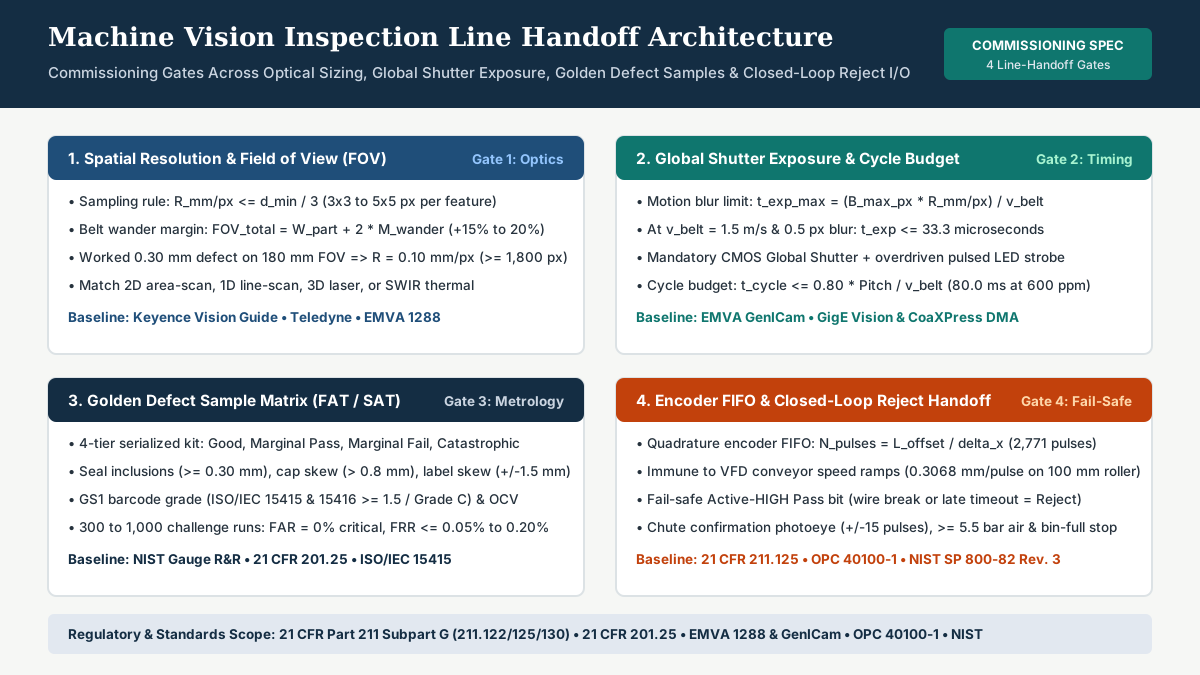
Commissioning a machine vision inspection station without locking spatial pixel resolution, strobed shutter timing, boundary defect samples, and encoder-tracked reject verification causes high-speed packaging lines to pass critical defects or choke on false-reject scrap. A camera that reads static cartons on a lab bench will fail at 600 packs per minute if conveyor vibration shifts the field of view, motion blur smears thermal-transfer date codes, or a variable-frequency drive (VFD) speed ramp causes the pneumatic reject pusher to fire late.
On food, beverage, pharmaceutical, and medical-device lines, automated vision inspection connects two distinct engineering domains: optical metrology inside the camera and deterministic actuator control inside the Programmable Logic Controller (PLC). Under 21 CFR Part 211 Subpart G (Sections 211.122, 211.125, and 211.130), drug manufacturers must inspect labeling and packaging for correct identity, lot number, and expiration date; Section 211.125(c) waives manual label reconciliation counts only when 100% electronic or visual verification operates on the packaging line during or after finishing operations. How local PLC control loops differ from supervisory monitoring paths is detailed in industrial IoT vs industrial automation on a plant floor, with companion automation explainers in the Technology section.
| Commissioning handoff domain | Engineering formula or rule | Production target benchmark | Controlling standard or reference |
|---|---|---|---|
| 1. Spatial resolution & Field of View (FOV) | R_mm/px <= d_min / 3 (3x3 to 5x5 px per minimum feature) across FOV_total = W_part + 2 * M_wander |
0.06 to 0.10 mm/px for a 0.30 mm seal or stroke defect; +15% to 20% lateral belt-wander margin |
Keyence Vision Guide & Teledyne Imaging Fundamentals |
| 2. Global shutter exposure & motion blur | t_exp_max = (B_px * R_mm/px) / v_belt with blur ceiling B_px <= 0.5 pixel |
t_exp <= 33.3 microseconds at v_belt = 1.5 m/s; CMOS Global Shutter + 5x to 20x overdriven pulsed LED strobe |
EMVA Standard 1288 & EMVA GenICam |
| 3. Deterministic frame-rate & cycle budget | t_cycle_max <= 0.80 * (Pitch_mm / v_belt) across trigger, exposure, DMA readout, inference, and PLC I/O |
<= 80.0 ms total cycle budget at 600 ppm (100 ms pitch interval), leaving 20% jitter headroom |
EMVA GenICam & OPC 40100-1 Machine Vision |
| 4. Golden defect sample matrix (FAT / SAT) | 4-tier serialized boundary kit: Good, Marginal Pass, Marginal Fail, and Catastrophic Fail |
0% False-Accept Rate (FAR) on critical defects; <= 0.05% to 0.20% False-Reject Rate (FRR) over 300 to 1,000 runs |
NIST Gauge R&R Handbook, 21 CFR 201.25 & ISO/IEC 15415 |
| 5. Encoder FIFO & closed-loop reject verification | N_delay = round(L_offset / delta_x_pulse) with Active-HIGH Pass bit and chute confirmation window +/-15 pulses |
Quadrature encoder tracking (0.3068 mm/pulse), >= 5.5 bar air interlock, chute photoeye, and bin-full line stop |
21 CFR 211.125, NIST SP 800-82 Rev. 3 & OPC 40100-1 |
Sizing spatial resolution, global shutter exposure, and frame-rate budgets
Specifying optics and timing for packaging line vision inspection starts from three physical quantities on the conveyor: the smallest defect dimension that quality assurance must reject (d_min), the maximum linear belt velocity (v_belt), and the center-to-center package pitch (Pitch_mm). Grounded in the Keyence Machine Vision Guide and Teledyne Vision Solutions Imaging Fundamentals, optical and cycle sizing follows three governing equations:
R_mm/px <= d_min / N_px_feature          (with N_px_feature = 3 to 5 pixels)
Pixels_horizontal >= (W_part + 2 * M_wander) / R_mm/px = FOV_total / R_mm/px
t_exp_max = (B_px * R_mm/px) / v_belt    (with B_px <= 0.5 pixel blur ceiling)
t_cycle_max <= 0.80 * (Pitch_mm / v_belt) = t_trig + t_exp + t_DMA + t_infer + t_PLC
In these equations:
d_minis the smallest physical defect feature to detect in millimeters (such as a0.30 mmheat-seal product inclusion or a broken thermal-transfer date-code stroke).N_px_featureis the minimum pixel sampling density across that feature (3pixels minimum for high-contrast blob detection;5pixels for grayscale edge metrology and Optical Character Verification, or OCV).R_mm/pxis the spatial resolution in millimeters per pixel at the object plane.W_partis the nominal package width in millimeters, andM_wanderis the lateral guide-rail or belt-wander tolerance on each side (15%to20%total FOV margin).B_pxis the maximum allowable motion blur in pixels during a single camera exposure (0.5 pixelfor barcode grading and OCV).v_beltis the linear conveyor speed in millimeters per second (v_belt = (CPM / 60) * Pitch_mm).t_exp_maxis the maximum camera shutter exposure time in seconds.t_cycle_maxis the deterministic inspection cycle ceiling in seconds, capped at80%of the nominal part-to-part interval to absorb mechanical pitch jitter.
Worked example: 600 ppm thermoformed pouch or carton line
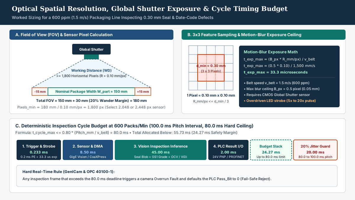
Consider a conditional calculation example for an automated vision inspection station mounted over a pouch or carton outfeed belt running at CPM = 600 packages per minute (10 packs/s) on a center-to-center pitch of Pitch_mm = 150 mm. The linear conveyor velocity is:
v_belt = (600 / 60) * 150 mm = 1,500 mm/s (1.5 m/s or 90 m/min)Suppose quality specifications require rejecting any heat-seal contamination inclusion or broken expiry character stroke down to d_min = 0.30 mm across a package width of W_part = 150 mm. Applying a 3-pixel minimum sampling rule (N_px_feature = 3, so each defect covers at least a 3 by 3 pixel block) sets the required spatial resolution:
R_mm/px = 0.30 mm / 3 px = 0.10 mm/px (or 0.06 mm/px at 5 pixels per feature)Adding a 20% lateral belt-wander margin (M_wander = +/-15 mm, so FOV_total = 150 + 30 = 180 mm) establishes the minimum horizontal sensor pixel count:
Pixels_horizontal >= 180 mm / 0.10 mm/px = 1,800 pixelsAn engineer therefore selects a standard 2,048 px (3.2 MP or 5 MP) or 2,448 px (5 MP) industrial CMOS sensor rather than a 1,280 px (1.3 MP) sensor that would clip package edges whenever a pouch drifts toward a guide rail. If the mechanical clearance above the conveyor fixes the working distance at WD = 300 mm and the chosen 2,048 px sensor has a 3.45 micrometer pixel pitch (W_sensor = 2,048 * 0.00345 = 7.07 mm), the thin-lens focal length identity f_mm = WD / (1 + FOV_total / W_sensor) specifies an 11.3 mm (standard 12 mm C-mount) low-distortion lens.
Next, holding motion smear during belt travel to B_px = 0.5 pixel (0.05 mm of travel during shutter open time) caps the camera exposure window:
t_exp_max = (0.5 px * 0.10 mm/px) / 1,500 mm/s = 0.0000333 s = 33.3 microsecondsA 33.3 microsecond exposure window forces two hardware decisions grounded in EMVA Standard 1288 radiometric characterization:
- Mandatory CMOS Global Shutter architecture: A rolling-shutter sensor exposes pixel rows sequentially across
2 to 10 ms; at1,500 mm/s, the bottom of a carton travels3 to 15 mmfarther than the top during readout, skewing 2D DataMatrix cells into unread parallelograms. A global-shutter CMOS sensor exposes and transfers charge for all pixel rows simultaneously. - Overdriven pulsed LED strobing: Because
33.3 microsecondscollects 30 times less light than a1.0 msexposure, ambient or continuous LED lamps leave the image underexposed and noisy under EMVA 1288 signal-to-noise ratio (SNR) criteria. Driving an industrial LED ring or bar light via a constant-current pulse controller at5xto20xits continuous current rating for a25 to 33 microsecondpulse (at a0.03%duty cycle when triggered at10 Hz) freezes package motion and suppresses ambient plant lighting variations.
Finally, at 600 ppm (10 packs/s), the nominal part-to-part pitch interval is 100.0 ms. Applying an 80% deterministic safety factor under EMVA GenICam acquisition rules caps the total processing cycle at t_cycle_max = 80.0 ms. How local sensor sampling intervals compare against PLC scan cycles is covered in choosing industrial IoT sensors for factory retrofits.
| Parameter | Symbol & formula | Worked value (600 ppm line) | Engineering consequence if violated |
|---|---|---|---|
| Line throughput & belt speed | v_belt = (CPM / 60) * Pitch_mm |
600 ppm at 150 mm pitch = 1,500 mm/s (1.5 m/s) |
Undersizing for nominal speed fails when accumulation recovery ramps the VFD to +15% catch-up speed |
| Minimum defect & spatial resolution | R_mm/px = d_min / N_px_feature |
0.30 mm / 3 px = 0.10 mm/px (0.06 mm/px at 5 px) |
At < 2 px per feature, sub-pixel edge contrast drops into sensor dark noise and causes missed defects |
| Total Field of View & sensor width | Pixels_min = (W_part + 2 * M_wander) / R |
(150 + 30) / 0.10 = 1,800 px (use 2,048 or 2,448 px sensor) |
Omitting the 20% wander margin clips date codes and seal corners when pouches skew on the belt |
| Maximum shutter exposure ceiling | t_exp_max = (B_px * R_mm/px) / v_belt |
(0.5 * 0.10) / 1,500 = 33.3 microseconds |
Exposure > 100 microseconds smears vertical barcode bars by > 1.5 pixels, dropping ISO grades below C |
| Deterministic cycle budget (80% cap) | t_cycle_max = 0.80 * (Pitch_mm / v_belt) |
55.73 ms allocated (0.233 ms trig/exp + 8.5 ms DMA + 45 ms infer + 2 ms I/O) vs 80.0 ms ceiling |
Any frame exceeding 80.0 ms overlaps the next part trigger, causing a GenICam frame-overrun fault |
Rule of thumb: Whenever linear conveyor velocity reaches 300 mm/s or calculated maximum exposure drops below 500 microseconds, eliminate rolling-shutter cameras and continuous LED lighting from the RFQ; specify a global-shutter CMOS sensor paired with an overdriven pulsed LED strobe controller.
Takeaway: Size horizontal sensor pixels for the full package width plus a 20% belt-wander margin at 3 to 5 pixels per minimum defect, cap exposure time so motion blur never exceeds 0.5 pixel, and keep total frame transfer plus inference below 80% of the minimum part pitch interval.
Matching area-scan, line-scan, 3D laser, and thermal vision to package defects
Not every packaging defect yields contrast under a standard 2D monochrome camera. Published packaging machinery benchmarks show that matching the sensor and illumination geometry to the physical defect mechanism determines whether an inline station holds a sub-0.2% false-reject rate or floods the reject chute with good product:
- High-speed bottling and precision labeling lines: Field data from Wolf Packing’s bottling-line vision analysis shows that labeling defects account for
15%to20%of rejected containers on beverage and personal-care lines running200to over1,000 containers per minute. While area-scan smart cameras (such as the Cognex In-Sight 9000) inspect flat front and back panels, cylindrical bottles require Basler or Teledyne DALSA 1D line-scan cameras triggered by rotary encoders to unwrap 360-degree label seams, or Keyence LumiTrax multi-angle structured lighting to isolate surface wrinkles from printed graphics. Replacing uncalibrated rule-based pixel thresholds with deep-learning edge models (such as Cognex ViDi trained on50to200defect images) tightens label-placement detection from2 to 3 mmdown to0.2 to 0.3 mmand cuts false-positive rejection rates from2.0%down to0.2%. - Pharmaceutical track-and-trace and blister lines: On the Antares Vision Group / Siempharma
ETF-300labeling and serialization platform (handling vials and bottles22 to 80 mmin diameter and40 to 180 mmtall at web speeds up to80 m/min), an endless infeed timing screw (auger) mechanically locks container pitch spacing before the containers pass the vision camera and reject station. On solid-dose Alu/PVC blister lines such as the CECLEDPP-260, an overhead area-scan camera inspects every formed pocket prior to foil lidding for missing capsules, broken tablets, color cross-contamination, and foreign particles, storing faulted coordinates in PLC memory until the punch outfeed station diverts the defective card. - Closure angle, 3D embossing, and opaque heat-seal integrity: Across the 65 vision OEMs indexed in the PMMI ProSource directory, specialized optical modalities handle non-flat or opaque barriers. Systems such as the KHS Innocheck CCI use infrared illumination to measure cap angle, crooked closures, and broken tamper-evident bands; 3D laser triangulation profilers (such as the Cognex In-Sight 3D-L4000 and Keyence LJ-X8000) project a blue (
405 to 450 nm) laser line to measure raised carton flaps (> 0.5 mm), dented cans, and low-contrast black-on-black embossed lot codes in true millimeter Z-height; and IPG Tishma thermal seal vision systems inspect opaque metallized pouches immediately downstream of the sealing jaws at up to500 ppm(while Optel InspectProof serialization cameras run at up to2,000 ppm).
When procuring industrial PCs (IPCs), frame grabbers, and edge vision controllers for these stations, teams should lock motherboard, GPU, and BIOS revisions and establish a 2% to 5% local Field Replaceable Unit (FRU) spare pool using the IT hardware distributor evaluation checklist.
| Imaging architecture & representative platforms | Sensor & hardware trigger mode | Illumination geometry | Target packaging defect scope | Dominant optical failure mode & engineering fix |
|---|---|---|---|---|
| 2D Area-Scan Smart Camera (Cognex In-Sight 2800/9000, Keyence CV-X/IV4, Omron MicroHAWK F430, Banner VE) | 2D CMOS Global Shutter (0.4 MP to 12 MP); 1 discrete photoeye or PLC position trigger per package |
Pulsed LED ring light, low-angle dark-field bar light, coaxial dome, or collimated telecentric backlight | Flat carton/pouch date & lot OCR/OCV, GS1 DataMatrix/1D barcode grading, blister pocket fill (CECLE DPP-260), and clear-film seal checks |
Specular hot-spot glare on glossy laminate or foil blinds OCV strokes; mount cross-polarized linear filters on both LED source and lens |
| 1D Line-Scan Camera with Rotary Encoder (Basler racer, Teledyne DALSA Linea, Krones Linatronic / Checkmat) | Single-row or trilinear CMOS (2k to 8k px wide, 20 to 140 kHz line rate); triggered line-by-line via RS-422 / HTL quadrature encoder |
High-intensity focused linear LED bar light aligned with the 1-pixel optical slit | Continuous web printing (> 2 to 5 m/s) and 360-degree unwrapped cylindrical bottle/vial label inspection on starwheels or spin belts |
Image stretching or compression during VFD speed ramps; wire quadrature encoder directly to the camera shaft-encoder divider input |
| 3D Laser Triangulation / Structured Light (Cognex In-Sight 3D-L4000, Keyence LJ-X8000 / LumiTrax) | 2D CMOS receiver paired with blue (405 to 450 nm) laser line; encoder-accumulated Z-height point cloud |
Narrow-band optical bandpass filter matched to laser wavelength, rejecting ambient factory light | Raised carton flaps (> 0.5 mm), cocked/high bottle caps (> 0.8 mm), black-on-black embossed codes, dented cans, and tray fill volume |
Laser shadowing behind tall bottle necks or deep tray rims; mount dual opposing laser heads or straddle the triangulation baseline angle |
Thermal / Short-Wave Infrared (SWIR) Seal Imaging (IPG Tishma Seal Vision, InGaAs 900 to 1,700 nm) |
Uncooled microbolometer thermal array or InGaAs SWIR camera mounted immediately after heated sealing jaws | Passive thermal emission from residual jaw heat, or active SWIR absorption illumination | Non-destructive detection of channel leaks, folded film pleats, and grease/sauce/powder trapped inside opaque foil seals up to 500 ppm |
Variable jaw dwell times during line stops shift seal baseline temperature; interlock thermal threshold to VFD speed and purge packs stopped in jaws |
Rule of thumb: Use 2D global-shutter area-scan cameras with cross-polarized strobes for flat printed codes and barcodes, switch to encoder-synchronized 1D line-scan whenever a defect wraps more than 120 degrees around a curved bottle, and specify 3D laser triangulation or thermal imaging when the defect is a height offset or trapped inside an opaque heat seal.
Takeaway: Select the optical modality that turns the physical defect into a high-contrast signal before writing software rules; algorithms cannot recover a 0.30 mm seal inclusion hidden behind opaque foil or specular film glare.
Building the golden defect sample matrix for FAT and SAT sign-off
A machine vision inspection system should never be signed off at Factory Acceptance Testing (FAT) or Site Acceptance Testing (SAT) by running a handful of pristine packages and waving a pen in front of the lens. Following the NIST/SEMATECH Gauge R&R and Measurement Process Characterization protocol, automated inspection equipment must be qualified for repeatability (equipment variation when measuring the identical physical reference specimen repeatedly at full speed) and reproducibility (stability across material lot variations, ambient lighting shifts, and operator recipe loads).
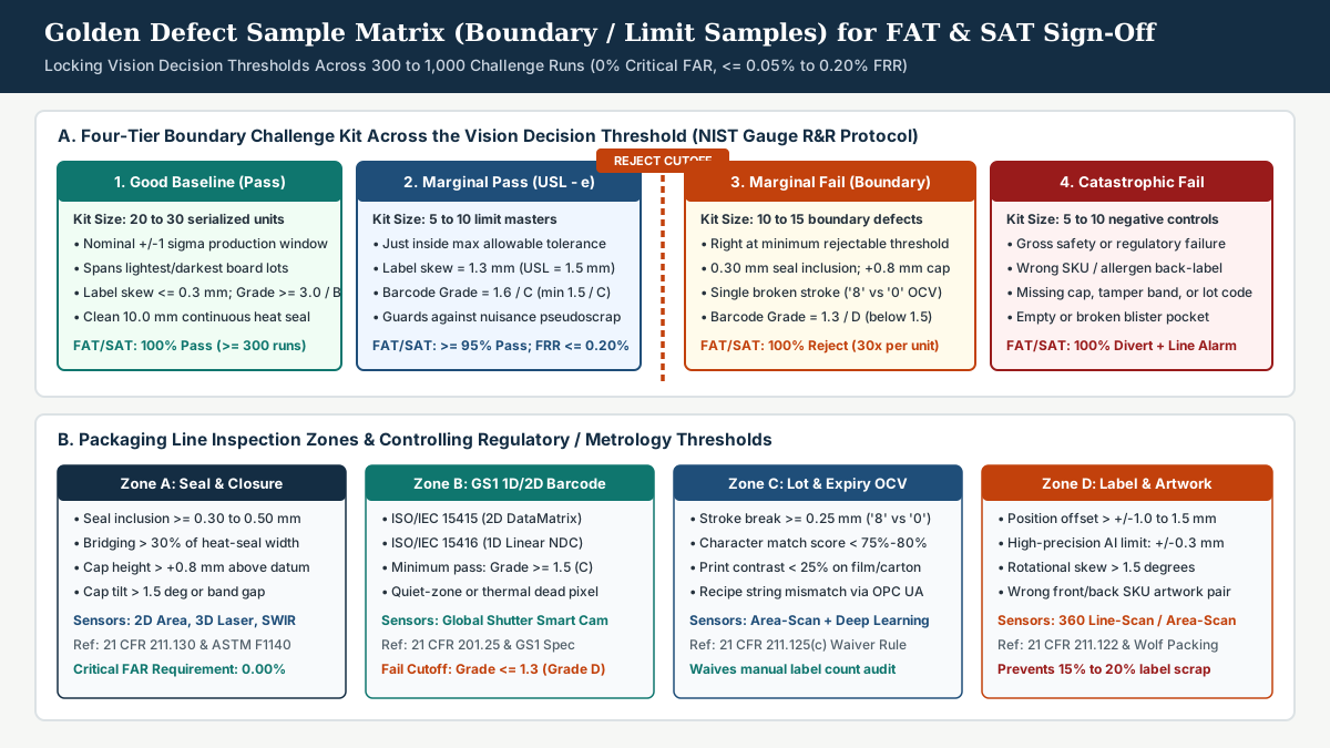
To execute a statistically valid Gauge R&R and vision qualification, packaging and quality engineers construct a serialized, physically preserved Golden Defect Sample Matrix (also called a Boundary or Limit Sample Kit) divided into four metrological tiers:
- Tier 1: Good Baseline (Nominal Pass,
20to30serialized units): Production packages centered within the+/-1 sigmaoperating window, deliberately spanning natural supplier material variation (the lightest and darkest paperboard lots, minimum and maximum glass mold seams, and fresh versus end-of-ribbon thermal transfer print). - Tier 2: Marginal Pass (Upper Specification Limit minus epsilon,
USL - epsilon,5to10master limit units): Engineered boundary packages sitting just inside the maximum allowable quality specification (for example, a label skewed by1.3 mmwhen the maximum allowable skew is1.5 mm, or a GS1 DataMatrix code verified offline atISO/IEC 15415 Grade 1.6 / Cwhen the minimum passing grade is1.5 / C). These samples prevent integrators from setting overly aggressive thresholds that pass defect challenges at the cost of high false-reject scrap during normal runs. - Tier 3: Marginal Fail (Minimum Rejectable Defect Threshold,
LSL + epsilon,10to15serialized challenge units): Engineered boundary defects sitting right at the rejection cutoff across each inspection zone: a0.30 mmproduct inclusion in the heat seal, a bottle cap cocked or unseated by+0.8 mm, a single broken stroke turning an expiry digit8into0, or a barcode graded at1.3 / D. - Tier 4: Catastrophic Fail (Gross Defect / Negative Control,
5to10serialized masters): Grossly non-conforming packages such as a missing label, an incorrect SKU or allergen back-label, a missing tamper-evident band, a completely blank date code, or an empty blister pocket.
Under 21 CFR 201.25, pharmaceutical barcodes encoding the National Drug Code (NDC) must remain machine-readable under GS1 or HIBCC standards across distribution, while 21 CFR 211.122 and 211.130 mandate strict prevention of labeling mix-ups and verification of lot and expiry codes. Budgeting for FAT/SAT challenge runs, customs clearance, and post-importation validation is detailed in total cost of importing industrial equipment, and balancing false-alarm technician labor against missed faults is analyzed in predictive vs preventive maintenance cost analysis.
| Inspection zone & sample tier | Physical defect features in challenge kit | Marginal pass limit (USL - epsilon) |
Marginal fail cutoff (Reject) |
FAT / SAT statistical acceptance gate |
|---|---|---|---|---|
| Heat seal & closure integrity (21 CFR 211.130, ASTM F1140) | Sauce, powder, or tablet dust in seal zone; channel wrinkles; cocked/high cap; broken tamper band | Seal inclusion <= 0.15 mm with >= 8 mm clear seal; cap height within +0.4 mm of datum |
Foreign inclusion >= 0.30 to 0.50 mm bridging > 30% of seal; cap height > +0.8 mm or tilt > 1.5 deg |
100% detection and physical diversion across 30 consecutive insertions per sample (0% critical FAR) |
| 1D / 2D barcode grading (21 CFR 201.25, ISO/IEC 15415 & 15416) | Low symbol contrast, quiet-zone encroachment, thermal printhead dead pixel line, duplicate serial | Offline verifier grade 1.6 to 2.0 (ANSI Grade C boundary) with intact quiet zone |
Overall ISO/IEC 15415 (2D) or 15416 (1D) symbol grade < 1.5 (Grade D or F) or wrong NDC/GTIN |
100% reject on Grade D/F or unread symbols; >= 98% pass on verified Grade C marginal-pass masters |
| Variable data OCR / OCV (21 CFR 211.125(c), OPC 40100-1) | Missing character stroke (8 read as 3 or 0), low contrast (< 25%), smeared CIJ/TIJ ink, wrong lot |
Character match confidence 82% to 85%; minor ink thinning < 0.10 mm with intact character topology |
Character confidence < 75% to 80%, stroke break >= 0.25 mm, or character string mismatch vs MES recipe |
0% False-Accept Rate (FAR) on wrong date/lot or unreadable digits across >= 300 seeded runs |
Label placement & artwork match (21 CFR 211.122, Wolf Packing / Antares ETF-300) |
Vertical/horizontal label offset, rotational skew, dog-ear corner lift, wrong SKU or allergen label | Position offset +/-1.2 mm (when USL = +/-1.5 mm) or +/-0.2 mm on high-precision AI lines |
Position offset > +/-1.5 mm (> +/-0.3 mm precision pharma/cosmetic), skew > 1.5 deg, or wrong pattern ID |
100% reject on wrong SKU/allergen artwork; overall line False-Reject Rate (FRR) <= 0.05% to 0.20% |
During the FAT and SAT execution run, quality engineers interleave the 30 to 50 serialized golden samples randomly into a stream of 300 to 1,000 normal production packages running at 100% nominal design speed (plus a catch-up overspeed test at 110% to 115% of nominal line rate). Every Marginal Fail and Catastrophic Fail unit must be both flagged by the camera and physically confirmed inside the locked reject bin (FAR = 0%). Simultaneously, the Good Baseline and Marginal Pass stream must achieve a False-Reject Rate (FRR, or pseudoscrap) at or below 0.05% to 0.20% (<= 1 to 2 false rejects per 1,000 good packs).
Rule of thumb: Never allow a vision vendor to tune inspection thresholds using only Good and Catastrophic Fail packages; without serialized Marginal Pass (USL - epsilon) and Marginal Fail boundary masters, the decision threshold floats arbitrarily and will either pass borderline defects or generate 1% to 2% false-reject scrap on shift two.
Takeaway: Lock a 30 to 50 unit serialized Golden Defect Sample Kit under QA custody before FAT, store each sample’s raw uncompressed reference image to run offline regression tests whenever a vision recipe changes, and require a periodic shift-start challenge test using 3 to 5 negative-control masters in production.
Engineering encoder shift-register tracking and closed-loop reject verification
Even when a camera classifies a defective package with 100% accuracy, the inspection fails if the physical reject mechanism fires early, fires late, loses compressed air, or allows a rejected carton to bounce back onto the outfeed conveyor. In RezPack’s high-speed cartoner diagnostic analysis, engineers document that open-loop reject outputs without physical diversion confirmation allow faulted cartons to bypass the bin during air-pressure dips or glue/flap jams; installing a dedicated reject confirmation sensor inside the bin entrance allows the PLC to verify physical diversion and immediately stop the packaging line and raise an alarm if the defective package fails to enter the chute.
Under NIST SP 800-82 Rev. 3, high-speed sensor-to-actuator control loops must execute deterministically on the local controller and fail to a known safe state when communications, power, or actuation media degrade. Meanwhile, the OPC 40100-1 (OPC UA for Machine Vision) companion specification separates supervisory recipe management, job handover, and result logging (ISA-95 Level 2/3) from hard real-time trigger and reject I/O (Level 1). How supervisory job and disposition records link to batch holds is covered in what digital manufacturing means on the factory floor, and how hardware fault verification differs from a software heartbeat is examined in self-service kiosk systems and remote fleet management.
Why timer delays fail and how quadrature encoder FIFO tracking works
A common commissioning mistake on retrofit lines is triggering the downstream pneumatic reject valve using a fixed millisecond timer delay (t_delay = L_offset / v_belt_nominal). At a nominal speed of v_belt = 1,500 mm/s across an L_offset = 850.0 mm distance between the camera optical axis and the reject pusher, a fixed timer waits 566.7 ms. If downstream case-packer accumulation causes the conveyor’s variable-frequency drive (VFD) to decelerate to 600 mm/s while a defective pouch is in flight, that pouch travels only 340 mm in 566.7 ms; the fixed timer fires the air blast into empty space or knocks a preceding good package into the scrap bin while the defective unit continues downstream to the customer pallet.
To make reject tracking independent of conveyor velocity, link a quadrature rotary encoder (HTL 24V or RS-422 differential, A/B channels) coupled to the conveyor drive or idler shaft directly to a high-speed counter input on the PLC or vision controller:
delta_x_pulse = (pi * D_roller_mm) / PPR_effective
N_delay_pulses = round(L_cam_to_reject_mm / delta_x_pulse)
N_fire_pulse = C_trig + N_delay_pulses - round((v_belt * t_valve_lead) / delta_x_pulse)
In this tracking model:
D_roller_mmis the pitch diameter of the conveyor drive or encoder tracking wheel in millimeters.PPR_effectiveis the effective encoder pulses per revolution evaluated by the high-speed counter.delta_x_pulseis the linear belt travel in millimeters per encoder pulse.L_cam_to_reject_mmis the physical centerline distance from the camera trigger photoeye to the reject nozzle or pusher face.C_trigis the latched high-speed encoder pulse counter value when the package breaks the camera trigger photoeye.t_valve_leadis the constant electromechanical response time of the pneumatic solenoid valve and cylinder (typically 8 to 12 ms), converted dynamically into lead pulses at the instantaneous belt speedv_belt.
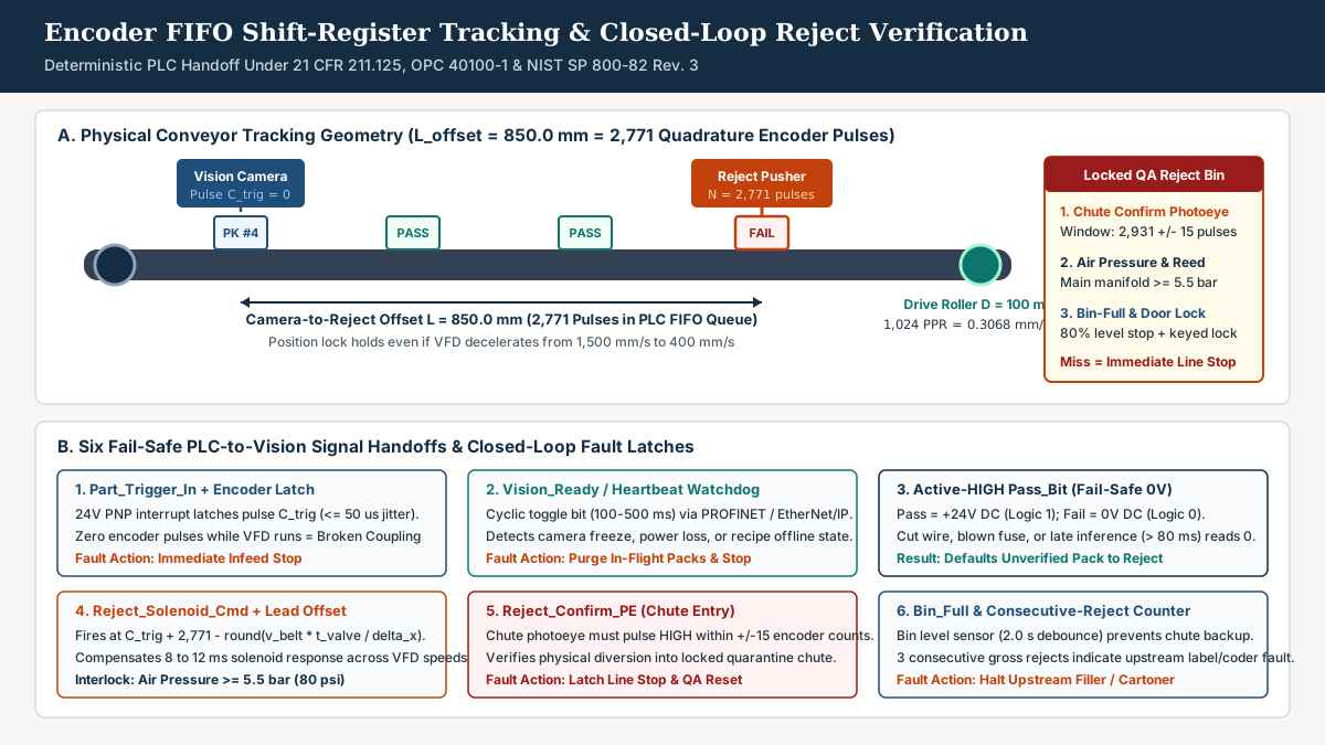
Worked example: In a conditional calculation example where L_cam_to_reject_mm = 850.0 mm, the conveyor drive roller has diameter D_roller_mm = 100.0 mm (circumference pi * 100.0 = 314.159 mm), and the shaft carries a PPR_effective = 1,024 pulses-per-revolution incremental encoder:
delta_x_pulse = 314.159 mm / 1,024 pulses = 0.3068 mm/pulse
N_delay_pulses = round(850.0 mm / 0.3068 mm/pulse) = 2,771 encoder pulses
When Package #4 breaks the trigger photoeye at encoder count C_trig = 10,000, the PLC inserts {Pack_ID: 4, C_trig: 10000, Status: Pending} into a First-In, First-Out (FIFO) shift register. Within 55.73 ms (182 encoder pulses at 1.5 m/s), the camera sets the status bit. If the package fails inspection (or if the camera fails to respond before the 80.0 ms / 261-pulse decision deadline), the PLC schedules the reject solenoid to fire at encoder count 10,000 + 2,771 = 12,771 (minus 49 lead pulses for a 10 ms solenoid opening delay at 1,500 mm/s, or 13 lead pulses if the belt has slowed to 400 mm/s). Finally, a Reject Confirmation Photoeye mounted inside the throat of the locked reject chute checks that the diverted package breaks its beam within Window_confirm = [12,916, 12,946] (2,771 + 160 +/- 15 pulses). If no pulse transition occurs inside that window, the PLC immediately halts the outfeed conveyor.
| Signal name & I/O layer | Direction & electrical interface | Deterministic timing requirement | Fail-safe interlock & line-stop action |
|---|---|---|---|
1. Part_Trigger_In & Encoder_A/B |
Field Photoeye & Shaft Encoder to PLC / Camera High-Speed Input (24V PNP interrupt + RS-422 / HTL quadrature) |
Hardware edge latch jitter <= 50 microseconds; logs C_trig into PLC FIFO shift register |
If VFD_Run = 1 but encoder pulse frequency drops to 0 Hz for > 200 ms (broken encoder belt or coupling), latch fault and stop infeed |
2. Vision_Ready & Heartbeat_Toggle |
Vision Controller to PLC (24V DO + cyclic PROFINET / EtherNet/IP watchdog bit every 100 to 500 ms) |
Watchdog timeout <= 1.0 s; confirms camera is in ContinuousExecution state (OPC 40100-1) |
If camera freezes, drops out of Run mode, or loses power, treat all in-flight packages in the FIFO queue as FAIL and halt upstream filler |
3. Result_Strobe & Pass_Bit (Active-HIGH) |
Vision Controller to PLC High-Speed Input (24V DC PNP discrete wire or deterministic Industrial Ethernet I/O frame) |
Must arrive before C_current >= C_trig + N_deadline (<= 80.0 ms); Pass = +24V (1), Fail = 0V (0) |
Wired Active-HIGH for Pass: a severed cable, blown fuse, or late inference timeout defaults the input to 0V (Fail), diverting the unverified pack |
4. Reject_Solenoid_Cmd & Air_Pressure_OK |
PLC High-Speed Output to Pneumatic Valve (24V DC DO with diode suppression) + Manifold Pressure Switch (24V DI) |
Fires at C_trig + N_delay - N_lead for 25 to 60 ms; air pressure switch set at >= 5.5 bar (80 psi) |
If manifold pressure drops below 5.5 bar or pusher cylinder reed switch fails to confirm full retraction within 100 ms, trigger immediate line stop |
5. Reject_Confirm_PE (Chute Entry) |
Reject Bin Throat Photoeye to PLC High-Speed Input (24V DC PNP background-suppressed sensor) |
Must pulse LOW -> HIGH -> LOW within encoder window [C_reject + N_chute - 15, C_reject + N_chute + 15] |
If Reject_Solenoid_Cmd fires but Reject_Confirm_PE detects no package entering the chute, stop outfeed belt immediately and require QA badge reset |
6. Reject_Bin_Full & Bin_Door_Locked |
Bin Level Photoeye & Keyed Guard Switch to PLC Control Input (24V DC DI) |
Continuous monitoring; Bin_Full beam blocked for > 2.0 s (debounced past falling packages) |
Halts line when bin reaches 80% capacity so stacked rejects cannot bounce back onto the main belt; logs QA key-switch access for 21 CFR 211.125 reconciliation |
Rule of thumb: Always wire the camera’s discrete Pass_Bit Active-HIGH (+24V = Pass, 0V = Fail) and initialize every new package entry in the PLC’s encoder FIFO shift register to 0 (Fail) at the moment the trigger photoeye fires; a package should only be permitted to stay on the conveyor if an explicit +24V Pass pulse overwrites that memory slot before the decision deadline.
Takeaway: Replace fixed timer delays with a quadrature encoder FIFO shift register, wire Pass signals Active-HIGH, and interlock the reject station with a chute confirmation photoeye, a 5.5 bar air-pressure switch, and a bin-full sensor so no uninspected or unverified defective package can reach finished-goods palletizing.