A monitoring retrofit can create production loss if its wiring, mounting or network connection disturbs the existing line. Choose industrial IoT sensors for factory retrofits by the measurement needed, the installation it requires and the failures it could pass into the PLC control path.
For an existing factory line, choose a separate monitoring sensor when it can capture the required physical signal without modifying control wiring. Reuse an existing signal only after checking its electrical interface and shared dependencies; use a PLC-network gateway only when the required data already exists and the communication boundary can be controlled. For IIoT sensors in manufacturing, acquisition bandwidth, installed mounting response and fault isolation matter more than a dashboard’s refresh speed. Record those requirements before selecting the sensor or connecting its gateway.
Reuse an analog signal, add a sensor or connect a gateway?
Choose the route that obtains the required measurement with the fewest new dependencies on the running line. The following comparison is an engineering review framework; the selected hardware drawings and plant change procedure determine the actual installation.
| Retrofit route | When it fits | What it still depends on | Dominant Failure Mode & Prevention |
|---|---|---|---|
| Tapping a spare analog input to acquire a signal | A suitable unused channel can receive a new sensor, or an approved interface can duplicate an existing analog signal for monitoring. | A PLC input still needs a data-export route; shared cards, power and signal interfaces remain dependencies. | Disturbing the original measurement through incorrect wiring, loading or shared faults. Check input type, grounds and loop burden; use a documented isolation/duplication interface where required and review its failure behavior. |
| A parallel clamp-on sensor with its own monitoring channel | A separate sensor can measure the required property through an approved non-intrusive installation. “Parallel” here means a second measurement path on the asset. | Mount security, usable measurement band, cable routing and monitoring power or battery service. | A loose or unsuitable mount produces misleading data or becomes a physical hazard. Verify the installed response and retention method; keep the monitoring assembly clear of moving parts and access routes. |
| A gateway on the PLC network | The PLC already exposes the required value with sufficient quality and timing for the monitoring task. | The controller, its communications service and the network segment carrying the data. | Excess requests or an unintended command path affects the existing system. Restrict permitted traffic and privileges, measure the communication load and approve reconnect behavior before production use. |
A spare analog input is a receiver, not a signal-copy output. Do not assume two current inputs can share an existing 4–20 mA loop by simply teeing the wires. Phoenix Contact’s public signal-duplicator documentation describes hardware for electrical isolation and duplication of analog signals; compatibility and fault behavior still require the chosen interface’s wiring and technical data. A duplicated output does not eliminate a shared transmitter or shared power supply.
The wider architectural distinction is covered in industrial IoT versus industrial automation.
Can the mounting remain non-intrusive and still measure the fault?
Accept a non-drilled mount only when its attachment and installed measurement response suit the intended observation. A mounting method that preserves the machine mechanically can still change the signal enough to hide useful information.
For vibration, PCB Piezotronics’ mounting guidance explains that a smooth, direct stud mount provides the broadest usable frequency range. Added mounting bases can lower the system’s resonance, while soft interfaces attenuate high-frequency transmission. Its magnetic-mounting section describes temporary attachment to suitable magnetic surfaces and calls for good surface contact. Those conditions apply to the mounting assembly; they do not establish a universal frequency limit for every retrofit sensor.
Mounting rule of thumb: if the mounting method changes from the configuration used to specify the sensor’s response, verify the assembled sensor-and-mount response before relying on its upper measurement band. Do not transfer a stud-mounted specification to a magnetic, adhesive or clamped installation without supporting data.
For retrofit sensors on the factory floor, record the measurement location, orientation, surface preparation, retention method and cable strain relief. Check whether removing a guard or servicing the machine will move the sensor. A vibration sensor on a flexible guard may describe that guard’s motion rather than the intended machine location; choose the location through the measurement plan.
If the proposed bracket needs extra holes in a guard, include the guard change and its review in the installation scope. Treat “no process penetration,” “no drilling” and “no control-wiring change” as separate requirements.

Which sample rate matters beside the PLC control cycle?
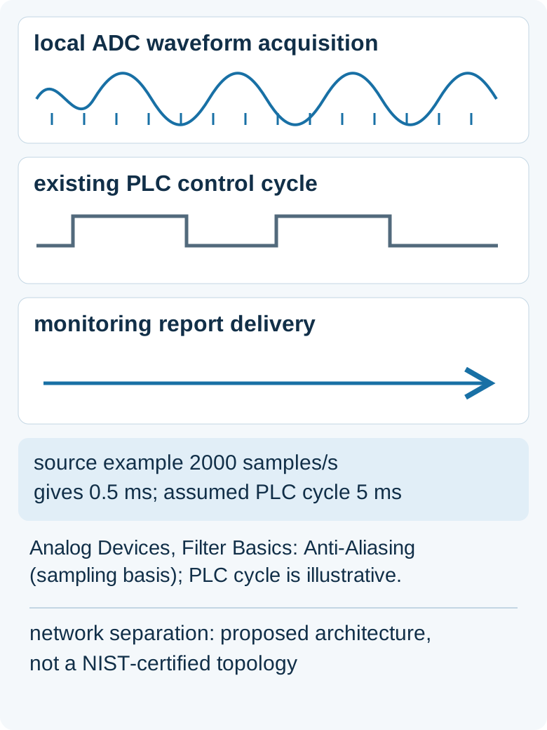
Specify local acquisition for the physical signal, then specify reporting for the decision it supports. An ADC’s sampling rate, the PLC’s control-cycle time and the dashboard’s update interval describe different events.
Analog Devices’ anti-aliasing note states: “The sample rate must be greater than or equal to two times the highest frequency component in the input signal.” It also calls for practical margin above that minimum and discusses filtering before conversion.
Sampling rule of thumb: for baseband waveform capture, if the highest required signal frequency reaches half the sampling rate, increase acquisition rate and review the anti-alias filter before accepting the measurement. Out-of-band energy must be controlled at acquisition; faster uploads cannot repair aliasing already present in the samples. A reported overall vibration value is also different from a raw waveform: establish which one the diagnostic task needs.
To compare sampling with an existing control cycle, use this dimensional identity, where Δt is the sample interval, f_s is samples per second and T_c is control-cycle time in seconds:
Δt = 1 / f_s; interval ratio R = Δt / T_c = 1 / (f_s × T_c).
Labeled-assumption arithmetic: use the note’s theoretical minimum example of f_s = 2,000 samples/s for a 1 kHz signal, and assume T_c = 5 ms solely for comparison: Δt = 1 / 2,000 s = 0.5 ms; R = 0.5 ms / 5 ms = 0.1.
That is ten sample intervals per assumed control cycle, with no assumed synchronization. It does not establish suitable practical sampling at the theoretical limit, delivery latency or permission to place a control function on the monitoring network. Record the sensor’s acquisition window, feature calculation and reporting schedule separately from the existing controller timing.
What actually isolates the monitoring path from the PLC?
Review electrical dependencies, application permissions and network boundaries separately. Passing one of those checks does not establish the others.
For the electrical path, trace the transmitter, power supply, isolator or duplicator, input card and grounding arrangement. Ask what the original control input sees if monitoring power fails or the added monitoring connection is removed. An isolator’s normal-operation description is insufficient evidence for every open-circuit, short-circuit or power-loss outcome.
For the application path, require the monitoring account to have only the access it needs. The OPC Foundation’s Address Space Model, including AccessLevelType and UserAccessLevel, distinguishes readable and writable values and user-specific access. Verify the actual server permissions; also check callable functions rather than assuming a read-only dashboard proves all commands are blocked. Read-only access still leaves a communications connection to review for load and availability.
For the network path, NIST SP 800-82 Rev. 3, section 6.2.1.3, describes mapping required communications and enforcing restrictions with isolation devices such as gateways and firewalls. Document permitted endpoints and traffic at each crossing. A gateway attached to the PLC network participates in that network even when its destination is only a historian.
Where the requirement is hardware-enforced outward-only transfer, NIST Appendix E.1.2 describes data diodes whose hardware prevents reverse transmission. That is a different boundary from application read permissions. Select the boundary from the plant’s requirements and supported architecture.
What belongs in the retrofit’s total cost?
Compare the complete installation and operating burden over the same period. A sensor budget that omits production interventions, guard work or another network connection understates the retrofit.
| Cost factor | What to include | Evidence to collect |
|---|---|---|
| False trips and unnecessary stops | Diagnosis time, operator response, restart work and scrap if an advisory alarm prompts a stop; direct control trips require a separately approved control change. | Alarm history with confirmed causes, response records and restart consequences. |
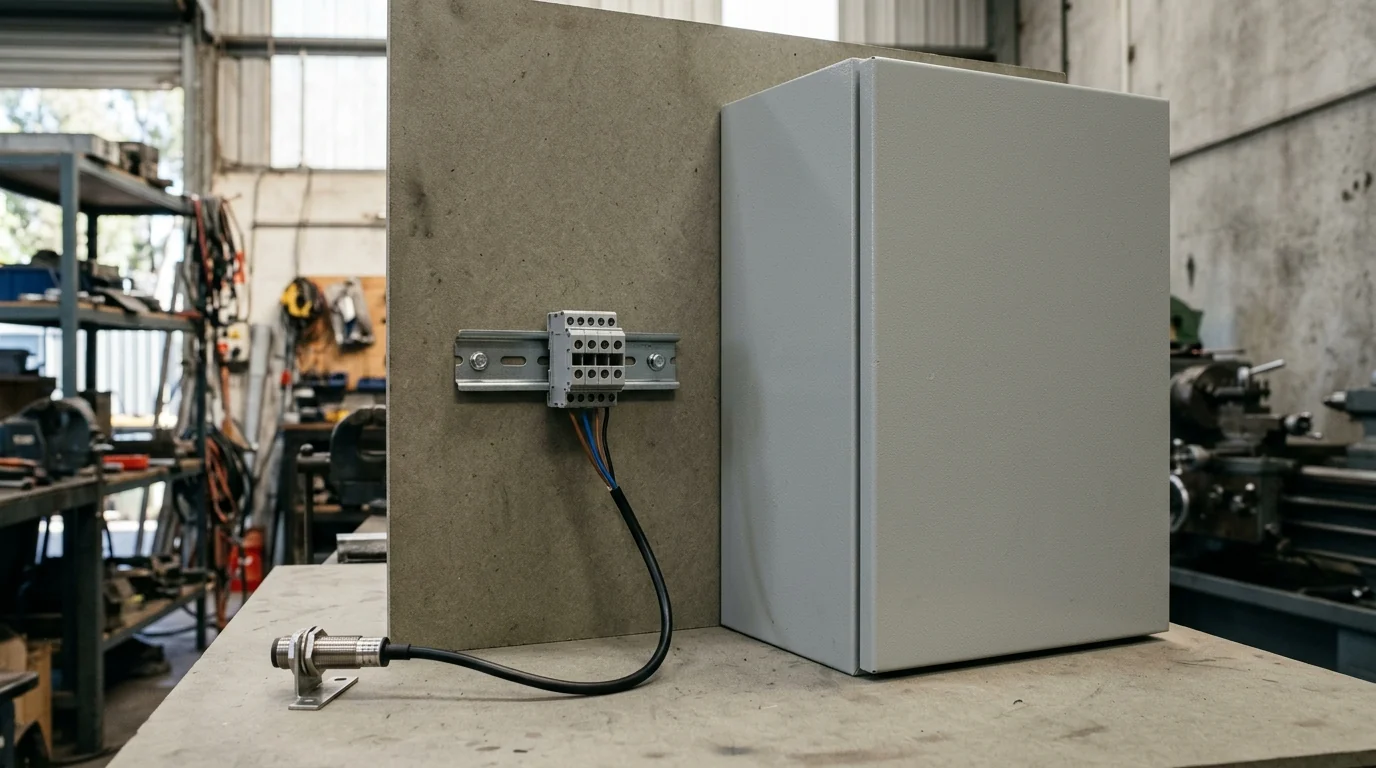
| Extra holes in a guard | Engineering review, approved fabrication, removal/refitting work and any new sensor-access burden. | The agreed mount drawing, guard-change decision and maintenance-access check. |
| A second network drop | Cable route, switch port, termination, boundary configuration, commissioning and ongoing support. | Approved network drawing, ownership and installation scope. |
| Signal reuse | Interface hardware, wiring work, outage access, calibration checks and retained shared dependencies. | Selected interface documentation and before/after signal checks. |
| Separate monitoring sensor | Mount preparation, power or battery service, cable inspection, data review and replacement access. | Service plan and named owner for data quality and alarms. |
Before accepting the retrofit, require recorded answers to four questions: does the installed mount preserve the required measurement band; does loss of monitoring leave the established control behavior within its approved design; are unauthorized writes and commands rejected; and are missing or stale measurements visible to the person using the trend? Plan interruption checks under the plant’s commissioning procedure, with review of controller and network load during normal operation and reconnects.
Further engineering explainers are in the Technology section.
Method and sources
This guide compares installation dependencies using public engineering documents accessed on 19 October 2026: NIST SP 800-82 Rev. 3, section 6.2.1.3 and Appendix E.1.2; PCB Piezotronics’ accelerometer mounting guidance; Analog Devices’ anti-aliasing note; Phoenix Contact’s analog signal-duplicator documentation; and OPC Foundation’s Part 3 Address Space Model. The comparison table, cost factors and commissioning questions apply those principles as engineering review steps.
The timing calculation uses the Analog Devices note’s theoretical sampling example and an explicitly assumed PLC cycle. It specifies no installed controller, vibration diagnostic band, enclosure rating or plant alarm threshold. Verify those quantities against the selected equipment and the line’s documented operating requirements.
Last updated: 19 October 2026.