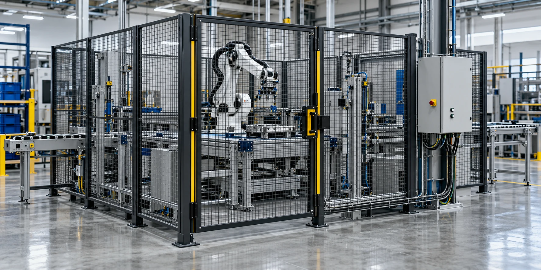
PLr is the performance level required to achieve the required risk reduction for each safety function. PL describes the ability of safety-related control parts to perform a safety function under foreseeable conditions. The achieved PL must satisfy PL ≥ PLr.
Use this guide to review a machine safety circuit: establish the target, examine the subsystem architecture, and assemble the validation record. For more engineering explainers, visit our Technology section.
Separate the target, the performance and the category
Category classifies a subsystem by its resistance to faults and subsequent behaviour in the fault condition. SRP/CS spans safety-related inputs through generation of safety-related outputs. An SRP/CS can include subsystems of different categories and subsystems with SIL classifications.
Keep separate entries for the required performance, the achieved performance and the category when reviewing the design.
Define the safety function before reviewing the circuit
Informative Annex A can be used to determine PLr unless a type-C product standard specifies it.
Use the following prompts to build a safety-function inventory. Repeat the record for each function under review.
| Inventory field | Specification content |
|---|---|
| Trigger | The safety-function specification identifies the triggering event. |
| Response and safe state | The specification includes permitted response time from demand to the safe state. |
| Operating modes | The specification identifies the operating modes in which the safety function must be active. |
| Interfaces | The specification identifies interfaces with machine control and other safety functions. |
| Demand rate | The specification includes the safety-function demand rate. |
Record the required performance beside the function description, then identify the input, logic and output under review.
Compare category architecture and possible performance
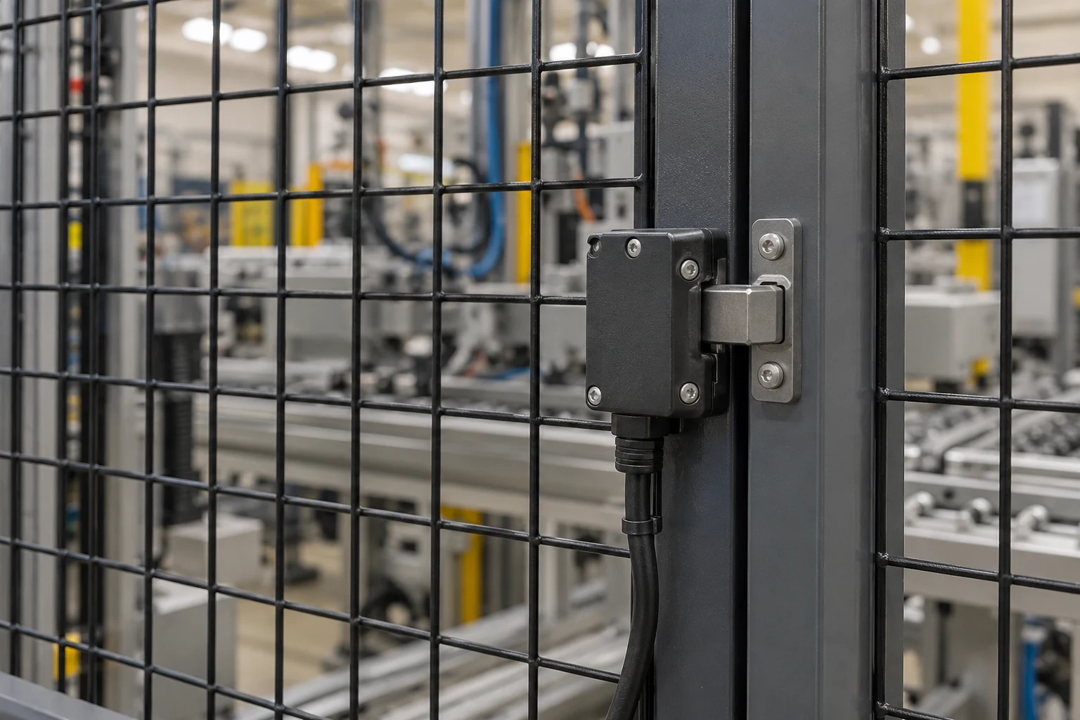
The designated architectures use Categories B, 1, 2, 3 and 4.
Read the performance column as an architecture capability boundary (they also apply when PFH is determined outside the simplified bar-chart method). Check the applicable reliability, diagnostic and common-cause-failure requirements before assigning achieved performance.
| Subsystem category | Architecture or fault behaviour | Possible performance |
|---|---|---|
| B | The designated Category B architecture is single-channel. | Category B can achieve a maximum PL = b. |
| 1 | Category 1 uses well-tried safety components and principles. Category 1 uses the same designated architecture as Category B. | Category 1 can achieve a maximum PL = c. |
| 2 | A fault can cause loss of the subfunction between tests. | Category 2 can achieve a maximum PL = d. |
| 3 | A single fault must not cause loss of the safety function. Where reasonably practicable, a single fault must be detected at or before the next demand. Accumulation of undetected dangerous faults can lead to a hazardous situation. | Category 3 can achieve PL = e. |
| 4 | Accumulation of undetected faults must not cause loss of the safety function. Both channel MTTFD and DCavg must be high. | Category 4 can achieve PL = e. |
For the final category, the undetected-fault accumulation requirement applies where detection of the individual fault is not possible.
Compare the architecture with its actual evidence. Do not substitute the possible performance in this table for the achieved-performance record.
Check the testing conditions for Category 2
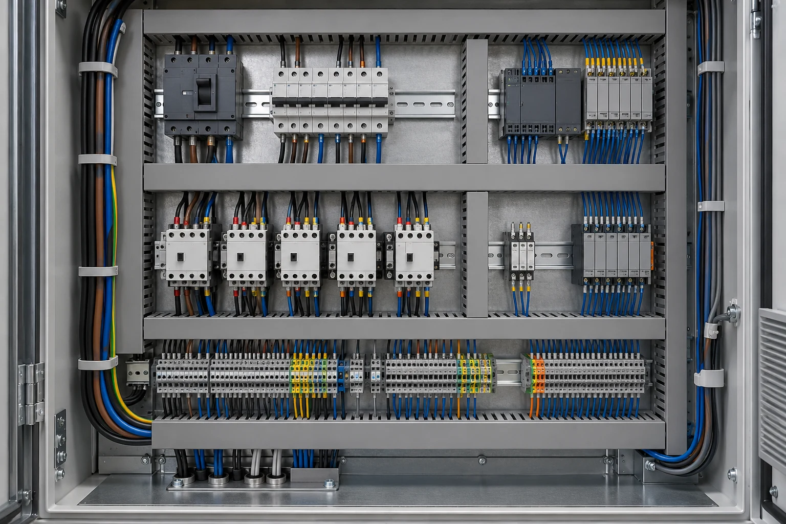
Review these conditions together:
- Each part of the functional channel requires at least low diagnostic coverage: 60% fault detection.
- The test rate must be at least 100 times higher than the demand rate, or testing occurs immediately upon demand of the safety function and prevents the hazard.
- Test-channel mean time to dangerous failure must exceed half that of the entire functional channel.
Appendix K describes an exceptional test rate only 25 times higher.
Keep the exceptional case separate in the review record; identify the applicable conditions before using it.
Inspect diagnostics, reliability and common cause measures
MTTFD means mean time to dangerous failure. Diagnostic coverage concerns the extent of fault detection mechanisms.
The diagnostic-coverage classes are:
- No diagnostic coverage: DC < 60 %.
- Low diagnostic coverage: 60 % ≤ DC < 90 %.
- Medium diagnostic coverage: 90 % ≤ DC < 99 %.
- High diagnostic coverage: 99 % ≤ DC.
The minimum CCF score is 65 points for subsystems in Categories 2, 3 and 4. Design process, operating stress, environment and operating procedures also affect dangerous failure frequency.
Collect the reliability inputs, diagnostic assessment and common cause measures alongside the architecture. Use a separate evidence entry for each subsystem.
Close the review with validation
Validation requires at least a functional test in addition to analysis, irrespective of category.
Use this architecture checklist to organize the review packet:
- Name the safety function and its triggering event.
- Record the intended safe state, permitted response time and active operating modes.
- Identify the control-system interfaces and demand rate.
- Record the required performance and identify the input, logic and output.
- Attach the category assessment, reliability inputs, diagnostic evidence and common cause measures.
- Compare achieved performance with the requirement.
- Attach the analysis and functional-test record.

What operation does the methodology cover?
The methodology applies to high demand and continuous operation. Its scope includes electrical, hydraulic, pneumatic and mechanical technologies. The methodology includes software design. Low demand operation is outside the scope.
Keep exploring the wider controls context in Industrial IoT vs Industrial Automation.
Sources
- ISO — Safety of machinery: safety-related parts of control systems, public standard preview.
- DGUV/IFA — Fourth Edition of the machinery safety control standard, changes overview.
- DGUV/IFA — Funktionale Sicherheit von Maschinensteuerungen.