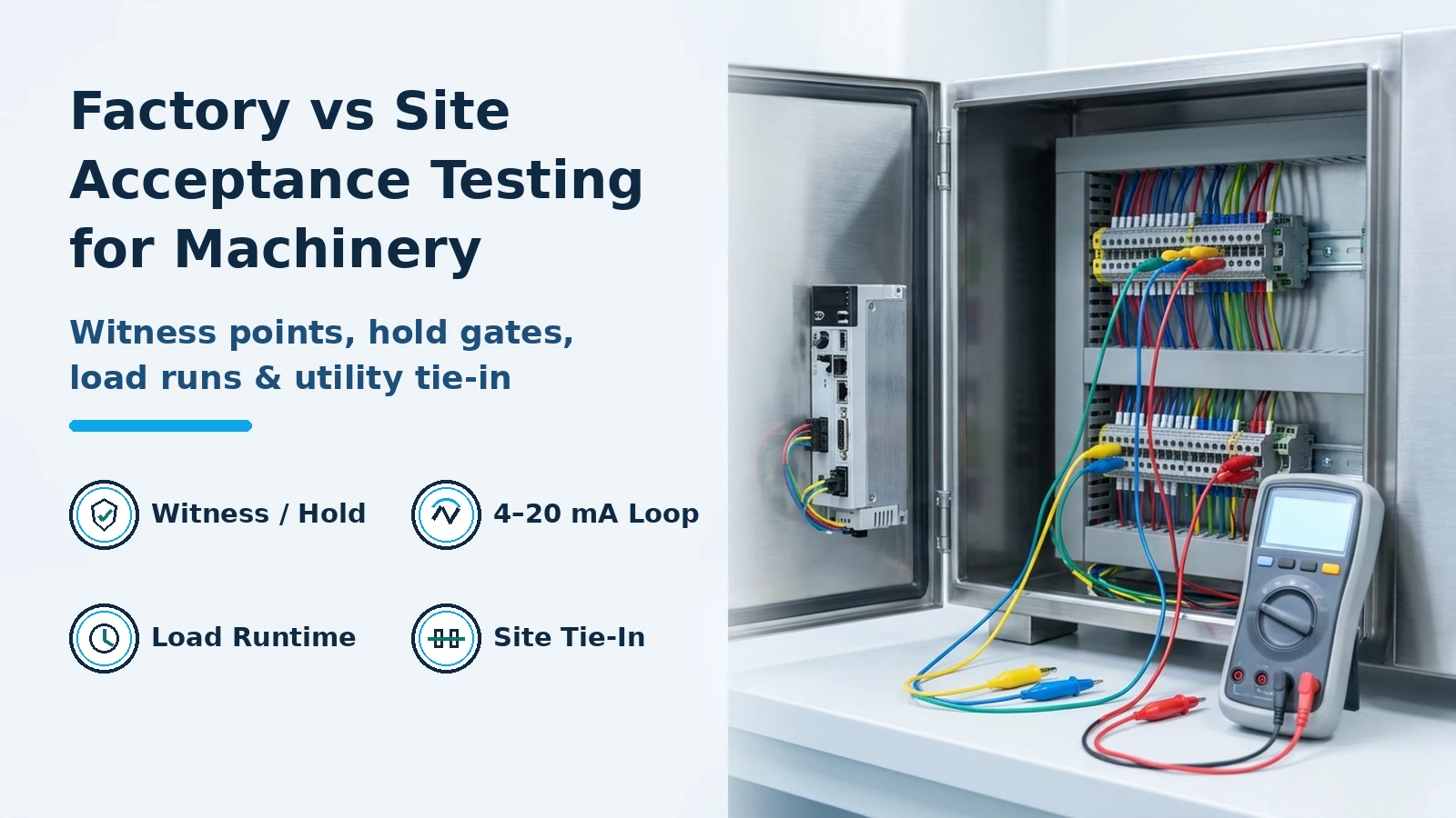
Treating factory acceptance testing as a brief, no-load demonstration causes latent wiring errors, mechanical jams, and utility mismatches to surface on the buyer’s plant floor, resulting in costly startup rework and multi-trade standby downtime. Separating a factory acceptance test (FAT) from a site acceptance test (SAT) requires assigning explicit Witness Points (W) and Hold Points (H) across the machine’s mechanical build, control-panel loop checks, extended load runs, and plant utility tie-ins before authorizing shipment or operational turnover.
In industrial equipment procurement, the acceptance sequence bridges two distinct commercial and technical boundaries. Customs valuation, freight, and tariff accounting through the buyer’s door—versus post-importation construction and assembly lines—are detailed in total cost of importing industrial equipment, while companion plant engineering guides appear in the Industry section. On the technical side, the U.S. Department of Energy (DOE) Design and Commissioning Report, Revision 2 (DOE-CNS-Commissioning-2019) and the International Society of Automation (ISA) InTech commissioning protocol divide machinery verification into six sequential gates from the vendor’s assembly bay to full production handover.
| Acceptance Gate & Location | Primary Verification Scope | Test Medium & Utility Supply | ITP Gate Type & Release Authority | Controlling Reference |
|---|---|---|---|---|
1. Hardware & Software FAT (HFAT / SFAT) — Vendor shop |
Enclosure layout vs. drawings, UL 508A fusing/torque, ground bonding, redundant PLC/PSU failover, digital I/O jumpers, 4–20 mA simulation at 4, 12, 20 mA (0%, 50%, 100%) |
Shop test bench power, handheld loop calibrator, jumper blocks | Hold Point (H) before panel energization; Witness Point (W) on loop simulation; dual sign-off on Document Approval Record |
ISA InTech (Fedenyszen, 2017) & OSHA 29 CFR 1910.147 |
| 2. Mechanical & Extended Load FAT — Vendor assembly bay | Continuous dry cycle (e.g., 24-hr benchmark), target rate run, fault/interlock script (mid-cycle E-stop, blocked sensors, starved infeed), changeover repeatability |
Vendor shop utilities + buyer-supplied actual product/packaging or density-matched simulant | Witness Point (W) on dry run; Hold Point (H) on load run and fault-recovery script |
DOE-CNS-Commissioning-2019 Sec. 1.5.3 & Rec. 7 & PMMI FAT Roadmap |
| 3. Pre-Shipment FAT Release — Vendor shipping bay | Travel bracing/locks, internal/external cleanliness, preservation medium (desiccant/N2), replacing temporary hydro gaskets with permanent service gaskets | De-energized, drained, dried, and preserved for transit | Hold Point (H): Active written Owner release required before crating and dispatch |
DOE-CNS-Commissioning-2019 Sec. 1.5.3 & NYSDPS ORES 21-00748 Sec. 7.4 |
4. Construction Acceptance Test (CAT) — Buyer plant floor |
Anchoring, removal of transit locks, utility tie-in verification (voltage/SCCR, air pressure/dew point, chilled water/steam), host-vendor LOTO exchange | Isolated plant utility drops verified up to machine main disconnects | Hold Point (H): Turnover from Construction/Rigging to Testing & Commissioning (T&C) |
DOE-CNS-Commissioning-2019 Sec. 1.5.4 & OSHA 29 CFR 1910.147(f)(2) |
5. Calibration, Grooming & Alignment (CG&A) — Buyer plant floor |
Laser shaft/conveyor alignment after transit, field instrument loop checks, VFD overcurrent settings, bumping motors for rotation direction, interlock dry checks | Live plant electrical and pneumatic supply under temporary LOTO test rules (1910.147(f)(1)) |
Witness Point (W) on motor bump; Hold Point (H) on safety interlocks before load run |
DOE-CNS-Commissioning-2019 Sec. 1.5.5 & 21 CFR 211.68 |
6. System & Integrated Operational Test (SOT / ISOT) — Buyer plant floor |
Full-speed line throughput under ambient plant temperature/humidity, upstream/downstream accumulation & starvation handoffs, O&M Systems Manual turnover | Live plant utilities + Integrated Water Run (IWR), simulant, or commercial production batch |
Hold Point (H): Formal turnover to Plant Operations (or Turn-Back if major defects appear) |
DOE-CNS-Commissioning-2019 Sec. 1.5.7–1.5.8 & ASHRAE Standard 202-2018 |
What Factory Acceptance Testing (FAT) and Site Acceptance Testing (SAT) Each Prove
A factory acceptance test and a site acceptance test are not duplicate runs of the same checklist. Each stage tests the engineering variables that are physically accessible—and cheapest to correct—at that location.
Under Section 1.5.3 of the DOE Design and Commissioning Report (DOE-CNS-Commissioning-2019) and ISA’s factory testing framework, FAT is conducted on the manufacturer’s premises before shipment to verify that the machine is complete, built to approved drawings and contract specifications, and functionally proven across its operating envelope. When a wiring reversal, mis-sized fuse, or mechanical cam interference appears during FAT, the OEM’s machine shop, electrical technicians, PLC programmers, and parts stock are feet away. Bypassing or compressing FAT transfers those defects to the buyer’s plant floor, where operations personnel, millwrights, electricians, and downstream equipment vendors are standing by on the clock during startup troubleshooting.
Once the machine is crated, transported, rigged onto the plant floor, and bolted down, SAT verifies everything that the builder’s shop floor could not replicate:
- Transit integrity and physical tie-in (
CAT, DOE Section 1.5.4): Confirming that road vibration or crane rigging did not rack the frame or shift shaft couplings, and that plant electrical feeders, compressed air headers, chilled water, steam, and exhaust ducts match nameplate ratings. - Pre-operational grooming (
CG&A, DOE Section 1.5.5): Verifying field sensor calibration, variable-frequency drive (VFD) and motor thermal overcurrent protection settings, motor rotational direction (“bumping” motors before coupling drive trains), and hardwired safety interlocks across interconnected line modules. - Integrated line behavior (
SOTandISOT, DOE Sections 1.5.7–1.5.8): Proving sustained production speed, product handling under actual plant temperature and relative humidity (such as hygroscopic powders or thin packaging webs), and buffer accumulation recovery between upstream infeed and downstream discharge machinery.
Conditional cost-exposure relationship: Factory fix vs. site standby delay
To evaluate whether to extend a factory test or defer verification to site startup, commissioning managers compare the direct cost of holding a machine at the vendor’s bay against the multi-trade standby and delayed-production exposure on the plant floor:
C_FAT_extension = D_ext * (R_vendor_bay + N_eng * R_travel_day)
C_SAT_rework    = H_rework * (R_trades_standby + R_ops_crew + L_unrecovered_margin) + C_expedite_parts
Net_Avoided_Loss = C_SAT_rework - C_FAT_extension
In this conditional planning relationship:
D_extis the number of additional FAT days added at the vendor’s factory to run extended continuous load and fault-script verification.R_vendor_bayis the daily vendor test-bay fee (zero when included in the base purchase order, or a contracted per-diem rate), andN_eng * R_travel_dayis the daily travel and lodging cost for the buyer’s witness team.H_reworkis the on-site troubleshooting and rework duration in hours when a defect escapes FAT and halts field startup.R_trades_standbyandR_ops_crewrepresent the hourly burdened cost of idle millwrights, electricians, system integrators, and plant operators waiting on site, whileL_unrecovered_marginis the hourly contribution margin lost only after scheduled startup buffer days are exhausted.C_expedite_partsis the air-freight and emergency machining cost to ship replacement components to the buyer’s facility.
Key takeaway: Whenever a mechanical, electrical, or PLC control function can be simulated or loaded on the builder’s floor, testing it at FAT isolates rework to a single vendor bay before multi-trade site labor and production schedules are exposed.
Witness Points vs. Hold Points in the Inspection and Test Plan (ITP)
Ambiguity over who can authorize a machine to advance to the next assembly stage—or leave the loading dock—is a primary cause of commissioning disputes. An Inspection and Test Plan (ITP) resolves this by classifying every inspection and test event as either a Witness Point (W) or a Hold Point (H).
As defined in Section 7.5 and Section 7.6 of the New York State Department of Public Service (NYSDPS) ORES Matter No. 21-00748 Quality Assurance and Control Plan, the ITP is maintained as a living document from pre-planning through pre-energization and functional testing. Both Witness Points and Hold Points are placed between multi-step fabrication, assembly, or installation stages where covering or advancing the work would require teardown if an earlier step failed. However, their contractual release authorities are fundamentally different:
- Hold Point (
H) — Mandatory Stop Requiring Active Written Owner Release: A Hold Point designates a critical verification step that requires an authority determined by the Owner—such as an Owner engineering representative, an Owner-appointed consultant, or an accredited third-party inspector—to issue a formal, written Hold Point Release before the work is covered, energized, or shipped. Neither the equipment manufacturer nor the site installation contractor can waive or self-release a Hold Point. - Witness Point (
W) — Advance Notice Required, Contractor Release Authority: A Witness Point designates a verification step where the vendor or contractor must notify the Owner’s representatives in advance following completion of internal quality-control checks so the Owner may observe the test. Crucially, the authority to release a Witness Point is pre-assigned to the Contractor or Vendor. If the Owner’s representative chooses not to attend or does not arrive at the scheduled window after proper notice, formal Owner sign-off is not required to advance; the contractor may proceed with subsequent stages at a calculated risk to maintain schedule flow.
Under NYSDPS Section 7.6, the Owner and Contractor review ITP designations at regular intervals. If an assembly sub-step designated as a Witness Point exhibits recurring non-conformances, the Owner upgrades that step to a Hold Point; conversely, once a vendor proves consistent repeatability across multiple identical skids, selected Hold Points can be relaxed to Witness Points.
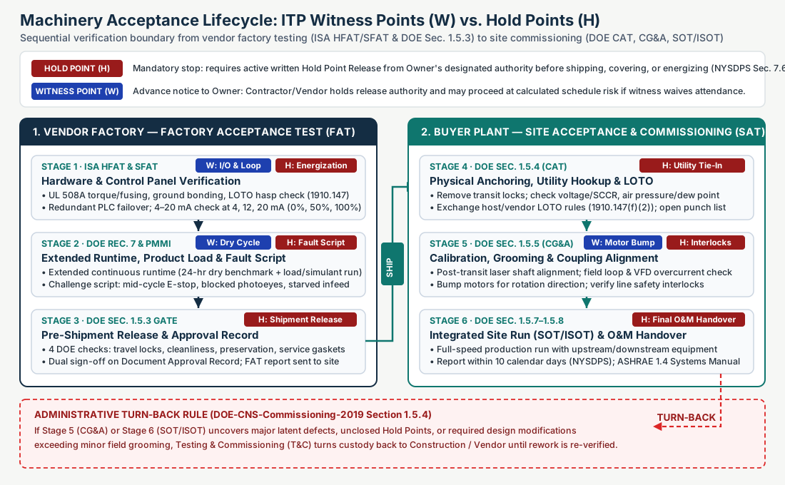
ITP Witness Point (W) and Hold Point (H) Allocation Matrix for Industrial Machinery
Plant engineering teams can adapt the following 10-gate allocation matrix when drafting the project ITP for packaging, processing, or automated assembly machinery:
| ITP Gate # | Verification Event | Phase | Recommended ITP Designation | Prerequisite Before Gate | Release Authority & Required Record |
|---|---|---|---|---|---|
| ITP-01 | Material certificates (MTRs), weld NDT, and product-contact finish audit (21 CFR 211.65 where applicable) |
Pre-FAT Fabrication | Hold Point (H) prior to passivation/enclosure closeout |
Vendor internal QC completion & heat-number traceability log | Owner QA / Third-Party Inspector written release on material dossier |
| ITP-02 | Control panel UL 508A torque/fusing audit, ground bonding, and short-circuit isolation (HFAT) |
FAT — Panel Shop | Hold Point (H) prior to first panel energization |
Approved electrical schematics & internal point-to-point ring-out | Owner Electrical Representative written release to energize |
| ITP-03 | Redundant PSU/PLC failover, digital I/O jumper test, and 4–20 mA loop scaling at 4, 12, 20 mA (SFAT) |
FAT — Panel Shop | Witness Point (W) (upgrade to H on custom safety PLC code) |
Completed HFAT release + uploaded PLC/HMI software revision |
Advance notice to Owner; signed ISA Document Approval Record I/O sheet |
| ITP-04 | Extended continuous dry-cycle mechanical run (e.g., 24-hr minimum dry cycle per PMMI benchmark) |
FAT — Assembly Bay | Witness Point (W) |
Internal mechanical alignment & lubrication check complete | Advance notice to Owner; continuous runtime & bearing temperature log |
| ITP-05 | Loaded product/simulant run, changeover demonstration, and deliberate failure/interlock script | FAT — Assembly Bay | Hold Point (H) |
Buyer product/packaging or approved surrogate delivered to vendor | Owner Operations & Engineering written sign-off on throughput & fault script |
| ITP-06 | Pre-shipment physical audit: travel bracing, cleanliness, preservation medium, service gasket installation | FAT — Shipping Release | Hold Point (H) prior to crating and freight loading |
All FAT open incidents closed; temporary hydro gaskets removed | Owner Representative written FAT Shipping Release (DOE Sec. 1.5.3) |
| ITP-07 | Construction Acceptance Test (CAT): anchor bolts, transit lock removal, utility header verification, LOTO exchange |
SAT — Pre-Commissioning | Hold Point (H) prior to connecting live plant utilities |
FAT report onsite (NYSDPS Sec. 12.1.9); host/vendor LOTO exchange |
Construction-to-T&C Administrative Turnover sign-off (DOE Sec. 1.5.4) |
| ITP-08 | Calibration, Grooming & Alignment (CG&A): laser coupling alignment, VFD overcurrent setup, motor bump rotation |
SAT — Grooming | Witness Point (W) |
CAT release signed; field instruments installed |
Advance notice to Owner T&C lead; signed alignment & rotation sheet |
| ITP-09 | Hardwired safety interlocks, E-stop circuit verification, and upstream/downstream signal handoff | SAT — Grooming | Hold Point (H) prior to introducing water, simulant, or product |
CG&A loop checks complete; guarding & LOTO devices verified |
Owner Safety & Engineering written release to start operational runs |
| ITP-10 | System / Integrated System Operational Test (SOT / ISOT) & Systems Manual turnover |
SAT — Final Handover | Hold Point (H) for transfer to Plant Operations |
Open punch-list items resolved; operator training completed | Final Owner Acceptance Release & functional report within 10 calendar days |
Why No-Load Factory Demos Fail at Startup: Hardware, Control Loop, and Runtime Verification
A machine cycling smoothly in the air for 30 minutes on a builder’s floor proves only that its drives turn under zero resistance. When that same machine reaches the buyer’s plant, three categories of hidden defects routinely derail startup: unverified control-panel scaling, thermal or mechanical drift during continuous duty, and untested fault-recovery logic.
1. Separating Hardware FAT (HFAT) and Software/Control FAT (SFAT)
In ISA’s InTech guidance (“Don’t rush to startup by passing the factory acceptance test”, Michael B. Fedenyszen, II), control system verification is split into a Hardware Factory Acceptance Test (HFAT) and a Software Factory Acceptance Test (SFAT) before mechanical runs begin:
- Hardware FAT (
HFAT): Commissioning engineers inspect the physical control enclosure against approved drawings for layout completeness, internal cleanliness, ground bonding, and short-circuit isolation before power is applied. When UL 508A industrial control panel compliance is specified in the contract, inspectors verify that fuse amperage ratings and terminal tightening torques are permanently marked inside the enclosure, that internal components carry required UL or FM approvals, and that the serialized UL 508A certification label is affixed. - Software and Loop FAT (
SFAT): Once energized, engineers test primary and redundant power supplies and PLC processors by pulling the primary module under load to witness bumpless failover and alarm generation. Digital inputs and outputs are exercised using temporary test switches and jumpers while verifying HMI screen indicators. For every 4–20 mA analog input loop, a precision loop calibrator injects 4.00 mA, 12.00 mA, and 20.00 mA at the field terminal blocks while the witness team verifies that the PLC code and HMI display exactly 0%, 50%, and 100% of the scaled engineering range (and tests out-of-range fault alarms below3.8 mAand above20.5 mA). Analog output channels are driven from the HMI at0%,50%, and100%while reading4 mA,12 mA, and20 mAwith a calibrated digital multimeter at the terminal strip.

2. Extending FAT Runtimes and Running Surrogate or Actual Loads
Brief vendor demonstrations miss heat buildup in servo gearboxes, pneumatic pressure droop during rapid valve cycling, and belt tracking drift. In Section 2, Recommendation 7 of DOE-CNS-Commissioning-2019, DOE commissioning lessons learned explicitly recommend that Commissioning Leads and Operations and Engineering personnel participate in selecting FAT test parameters and extend FAT runtimes beyond what the manufacturer normally offers for continuous-operating equipment.
In the packaging and processing machinery sector, PMMI (The Association for Packaging and Processing Technologies) recommends writing quantifiable FAT runtime and load criteria directly into the Request for Quotation (RFQ) and purchase contract:
- 24-hour minimum continuous dry cycle: Running the machine dry for at least 24 hours prior to witness arrival—or as the opening phase of FAT—to seat mechanical components and expose early infant-mortality drive or bearing faults.
- Actual product or engineered simulant runs: Shipping sufficient production-grade containers, film rolls, and product (plus a disposal plan for tested material) to the vendor plant. Where hazardous, sterile, or temperature-sensitive process media cannot be handled at the vendor factory, DOE Section 1.5.3 and Section 1.5.8 specify Integrated Water Runs (
IWRs) or density- and viscosity-matched surrogate simulants, while flagging any unverified temperature or bulk-density attributes as mandatory open test items for SAT. - Contractual re-test clause: Specifying in the purchase order that if the initial FAT fails to meet contracted acceptance criteria, the subsequent re-test FAT is provided at no additional vendor charge to the buyer.
3. Executing a Deliberate Failure and Interlock Script
A machine spends most of its production life recovering from upstream starvation, downstream backups, and material splices. During FAT, engineers and plant operators—who should attend FAT alongside project engineers to audit ergonomics and write One-Point Lessons (OPLs) for tool-less or multi-point changeovers—must execute a written failure challenge script:
- Mid-cycle emergency stop and recovery: Depress the E-stop pushbutton at peak speed, verify immediate safe de-energization, reset, and confirm the machine clears and restarts without crushing tooling, losing servo home positions, or passing unsealed/uninspected units.
- Sensor and photoeye obstruction: Block or disconnect each photoeye, proximity switch, and backup/starvation sensor one by one to verify that the PLC triggers the correct fault message on the HMI and halts the affected axis.
- Infeed starvation and discharge backup: Starve the infeed conveyor to confirm automatic standby mode and smooth auto-restart when product flow resumes; block the outfeed to verify high-level accumulation stop.
- Material and tooling fault injection: On web, filling, or assembly machinery, intentionally break the film web, trigger an auto-splicer at
50%roll depletion, disable a cutoff knife to verify uncut-pack detection, remove the lot/date code ribbon to confirm missing-code rejection, and run at both minimum and maximum catalog speed limits.
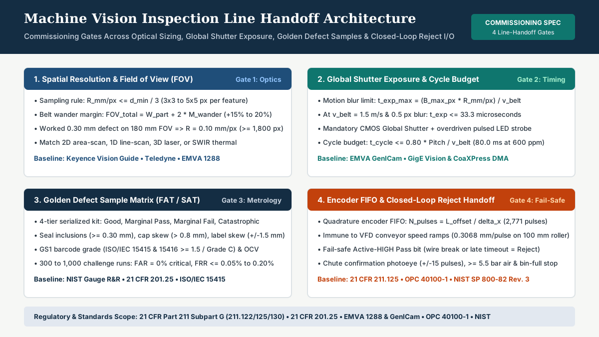
For automated optical inspection stations mounted on the machine, boundary challenge testing requires a serialized golden defect sample kit (Good, Marginal Pass, Marginal Fail, and Catastrophic Fail) paired with quadrature encoder FIFO reject verification, as detailed in machine vision inspection line handoff.
Conditional calculation example: Sizing FAT product shipment and analog loop scaling
Suppose a plant engineering team is preparing for the FAT of a continuous-motion liquid filling and capping monoblock rated at a nominal speed of CPM = 150 containers per minute with a 4-hour continuous loaded run requirement (t_load = 240 minutes) plus three 15-minute fault-script and speed-boundary runs (t_fault = 45 minutes at an average 80% effective throughput factor eta = 0.80), filling V_unit = 0.50 L per container. If the product cannot be recirculated after capping because capping torques deform the tamper-evident neck band, the minimum consumable container count (N_containers) and product volume (V_total) required on the builder’s floor for a single pass are:
N_containers = (CPM * t_load) + (CPM * t_fault * eta)
             = (150 * 240) + (150 * 45 * 0.80) = 36,000 + 5,400 = 41,400 containers
V_total      = N_containers * V_unit = 41,400 * 0.50 L = 20,700 L (approx. 5,468 US gallons)
Because shipping 20,700 L of live product and disposing of 41,400 capped bottles at an OEM shop is logistically prohibitive for many buyers, this simple arithmetic forces an upfront engineering decision in the ITP:
- Option A (Recirculating surrogate + boundary live batch): Run
210 minutesof the endurance test using a recirculated water/viscosity simulant through uncapped sample bottles (requiring only a closed-loop tote and500reusable test bottles), followed by a30-minute(4,500-container,2,250 L) non-recirculated live product and live cap torque verification run at FAT, while designating full-shift live product endurance as a Hold Point (H) at SAT. - Option B (Analog loop scaling formula during
SFAT): For the filler’s manifold pressure transmitter rated0.0 to 6.0 barover a4–20 mAloop, linear engineering scaling follows:
PV_eng = PV_min + ((I_mA - 4.0) / 16.0) * (PV_max - PV_min)Injecting 4.00 mA, 12.00 mA, and 20.00 mA at the PLC terminal block during SFAT must display 0.00 bar (0%), 3.00 bar (50%), and 6.00 bar (100%) on the HMI within the analog input card’s specified tolerance band before any fluid enters the manifold.
Mechanical, Utility, and Hazardous Energy Handoff Boundaries Between Vendor and Plant
The highest-risk phase of machinery commissioning is the physical handoff between the end of factory testing and the start of site energization. Two federal regulatory frameworks and four DOE pre-shipment physical checks govern this boundary.
1. The Four Overlooked Pre-Shipment FAT Release Checks (DOE Section 1.5.3)
In Section 1.5.3 of DOE-CNS-Commissioning-2019, DOE notes that commissioning teams routinely concentrate on functional performance during FAT while overlooking four physical release prerequisites that damage equipment in transit or contaminate plant startups:
- Suitability of the equipment to travel: Installing rigid structural shipping brackets, load-cell transport stops, servo-axis mechanical locks, and vibration-damping skids so road shock does not brinell bearings or fracture load cells.
- Degree of cleanliness: Flushing, wiping down, and drying internal chambers, manifolds, and sumps after factory water or product runs so stagnant test fluid does not corrode surfaces or harbor biological growth during ocean or highway transit.
- Preservation medium: Applying the specified transit preservation medium—such as vapor-phase corrosion inhibitors (VpCI), desiccant packs inside sealed barrier foil, or a positive-pressure dry nitrogen blanket—and tagging all ports that must be vented or purged before site startup.
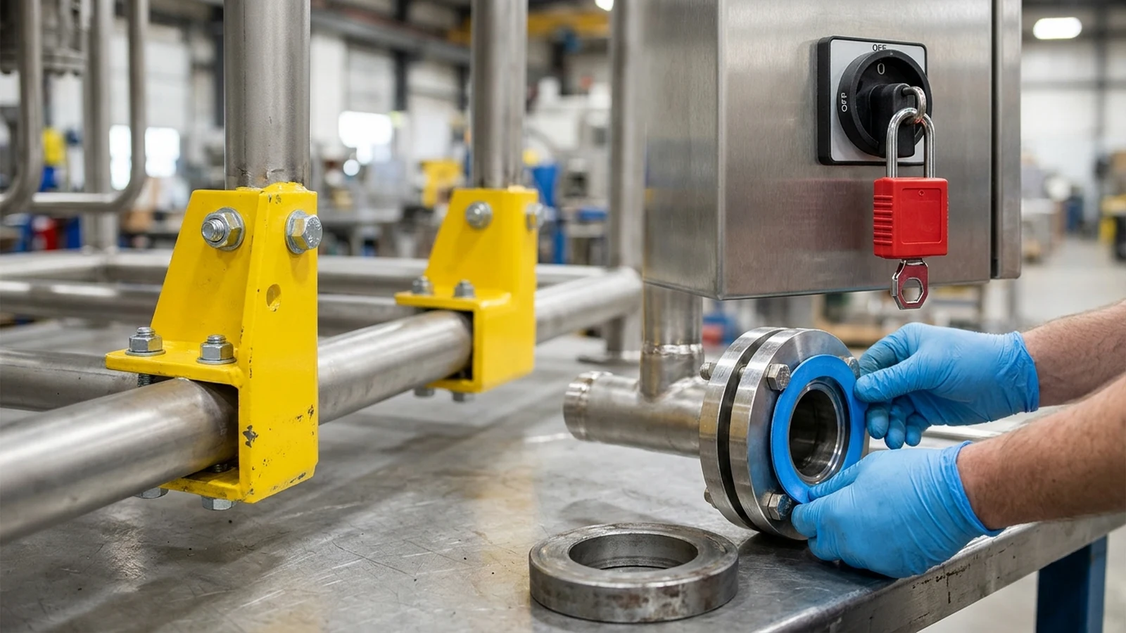
- Removal of temporary hydrostatic-test gaskets and installation of permanent service gaskets: Vendors frequently use sacrificial elastomer or temporary ring gaskets during factory hydrostatic pressure testing (
HFAT). Leaving temporary hydro gaskets in flanged joints causes process leaks or elastomer degradation once exposed to plant steam, solvents, or clean-in-place (CIP) chemicals at SAT. Inspectors must witness the removal of temporary test gaskets and verify that permanent, specification-grade service gaskets are installed and torqued.
2. Hazardous Energy Isolation (LOTO) Verification Under OSHA 29 CFR 1910.147
Both FAT safety walkdowns and SAT commissioning are governed by OSHA 29 CFR 1910.147 (The Control of Hazardous Energy — Lockout/Tagout):
- All energy sources and lockout hardware capability (
1910.147(b)&(c)(2)(iii)): Energy isolation audits at FAT must verify physical disconnect points not only for main electrical feeders, but also for compressed air (including quick-dump exhaust valves that bleed trapped downstream pneumatic pressure), hydraulic accumulators, gravity-drop mechanical heads, thermal heaters, and chemical lines. Under29 CFR 1910.147(c)(2)(iii), energy-isolating devices on newly installed or modified machinery must be designed to physically accept a lockout device. - Control circuits are NOT energy-isolating devices (
1910.147(b)): OSHA explicitly defines that push buttons, selector switches, and other control-circuit type devices are not energy-isolating devices. Relying on an HMI screen stop or an E-stop pushbutton while reaching into a seal jaw or conveyor drive during FAT or SAT adjustment violates federal lockout rules. - Five-step temporary LOTO removal during commissioning tests (
1910.147(f)(1)): When lockout/tagout devices must be temporarily removed during FAT or SAT to energize and test or position a machine component,29 CFR 1910.147(f)(1)(i)–(v)mandates five sequential steps:- Clear the machine or equipment of tools and materials;
- Remove employees from the machine or equipment hazard area;
- Remove the lockout or tagout devices as specified in the energy-control procedure;
- Energize and proceed with testing or positioning;
- De-energize all systems and reapply energy-control measures to continue servicing or adjustment.
- Host plant and outside vendor LOTO coordination (
1910.147(f)(2)): Whenever visiting OEM technicians or system integrators perform SAT activities on the buyer’s floor, the on-site employer and the outside servicing employer must inform each other of their respective lockout or tagout procedures and ensure personnel comply with the coordinated energy-control plan.
3. Regulated cGMP Equipment Boundaries Under 21 CFR Part 211 Subpart D
For pharmaceutical, medical-device, and cGMP packaging or processing machinery, acceptance protocols must also incorporate the federal equipment requirements in 21 CFR Part 211 Subpart D (§§ 211.63, 211.65, 211.67, and 211.68):
- Non-reactive contact surfaces and lubricant isolation (
§ 211.65): Verify at FAT that product-contact surfaces are non-reactive, non-additive, and non-absorptive, and that gearboxes, bearings, and pneumatic exhausts are physically isolated or fitted with food/USP-grade catch pans so lubricants or coolants cannot contact product or containers. - Written cleaning and disassembly verification (
§ 211.67): Witness a physical teardown and reassembly of product-contact parts during FAT to validate the vendor’s written disassembly, cleaning, and sanitizing instructions before the machine ships. - Automated/PLC controls, I/O accuracy, and backups (
§ 211.68): Confirm role-based password access so only authorized personnel can change master recipe parameters, verify input and output accuracy checks, and capture a verified backup copy of the PLC, motion-controller, and HMI code at both FAT sign-off and SAT completion. How controlled work instructions and hold-on-missing-inspection-result rules operate once the line enters daily production is explained in what digital manufacturing means on the factory floor.

Punch Lists, Turn-Back Rules, and the FAT/SAT Release Checklist
Moving a machine from the vendor’s shipping dock through field installation and into Plant Operations requires strict administrative control over open deficiencies and turnover documentation.
1. FAT Documentation Prerequisite and the Administrative “Turn-Back” Rule
Under Section 7.4 and Section 12.1.9 of the NYSDPS Quality Assurance and Control Plan and Section 2 of DOE-CNS-Commissioning-2019, complete vendor manuals and signed FAT reports must be delivered to the project site before system turnover. DOE’s commissioning review specifically identifies missing vendor manuals and absent FAT test records at the jobsite as a recurring root cause of startup delays.
When a machine transitions on site from the installation crew (Construction) to the Testing & Commissioning (T&C) group, DOE Section 1.5.4 mandates a formal administrative turnover procedure that:
- Defines exact physical and electrical jurisdictional boundaries (tagging which disconnects and isolation valves belong to
T&Cvs. Construction); - Logs all open deficiencies into a tracked turnover punch list (in complex facility startups, such as DOE’s Advanced Mixed Waste Treatment Project case study, the operations and testing team tracked and closed a 380-item turnover punch list prior to integrated simulant runs);
- Establishes a formal turn-back process. If
CG&AorSOT/ISOTtesting uncovers major latent defects, unclosed Hold Points, or required design modifications that exceed minor commissioning adjustments, theT&Clead executes a formal turn-back, returning physical custody and lockout control to Construction or the OEM vendor until rework is completed and re-inspected.
2. Final Handover to Operations and Maintenance (ASHRAE Standard 202-2018 & NYSDPS Sec. 12.1.11)
Following successful completion of on-site functional testing (SOT/ISOT), NYSDPS Section 12.1.11 sets a project governance benchmark requiring formal functional test reports to be submitted to the Owner within 10 calendar days of test completion.
Per the Whole Building Design Guide (WBDG) / National Institute of Building Sciences (NIBS) commissioning framework and ASHRAE Standard 202-2018 Table A-1, final acceptance integrates the Owner’s Project Requirements (OPR), Basis of Design (BOD), Construction Checklists, Functional Performance Test (FPT) data submittals, the closed Issues and Resolution Log, operator training records, and the Systems Manual (compiled per ASHRAE Guideline 1.4). Once Plant Operations signs the final Hold Point release, the baseline vibration, temperature, and cycle-time measurements captured during SAT become the reference dataset for ongoing reliability management—where engineering teams decide between calendar-based tasks and sensor-driven monitoring as analyzed in predictive vs preventive maintenance cost.
Actionable Deliverable: Machinery FAT & SAT Function, Witness/Hold Point, and Release Checklist
Attach or adapt the following verification table inside your equipment Request for Quotation (RFQ) and project Inspection and Test Plan (ITP). Project-specific numerical targets ([Project URS / Nameplate Entry]) are filled in from the contract specification and machine nameplate prior to test execution:
| Check ID | Verification Domain & Test Item | Phase (FAT / SAT) |
ITP Gate (W / H) |
Acceptance Criterion & Standard Reference | Project Target / Nameplate Entry | Sign-Off & Date |
|---|---|---|---|---|---|---|
| CHK-01 | Control Panel Hardware (HFAT): Enclosure layout vs. as-built schematic, ground bonding, short-circuit isolation, UL 508A fuse amperage & terminal torque markings |
FAT |
Hold (H) before power-on |
Zero wiring discrepancies; UL 508A label affixed; torque marks verified (ISA InTech HFAT protocol) |
[Panel SCCR & Voltage Entry] |
[Owner QA / Date] |
| CHK-02 | Hazardous Energy Isolation (LOTO): Lockable hardware capability on electrical, pneumatic (with pressure bleed), hydraulic, and thermal disconnects |
FAT & SAT |
Hold (H) |
All energy-isolating devices accept physical locks; pushbuttons/E-stops excluded as isolation devices (OSHA 29 CFR 1910.147(b), (c)(2)(iii)) | [List Disconnect Tag IDs] |
[Safety Lead / Date] |
| CHK-03 | Control & Analog Loop Simulation (SFAT): Primary/redundant PSU & PLC failover; digital I/O jumper checks; 4–20 mA injection at 4, 12, 20 mA (0%, 50%, 100%) |
FAT |
Witness (W) / Hold (H) |
Bumpless PLC failover; HMI displays 0%, 50%, 100% within card accuracy; analog outputs verified by meter (ISA InTech SFAT) |
[Loop Tag List & Tolerance] |
[Automation Eng / Date] |
| CHK-04 | cGMP Surface, Cleaning & Code Backup (where applicable): Product-contact MTRs, lubricant isolation, teardown/cleaning walkthrough, PLC password & backup archive | FAT & SAT |
Hold (H) |
Non-reactive contact surfaces; zero lubricant path to product; validated cleaning SOP; verified PLC/HMI backup (21 CFR 211.65, 211.67, 211.68) | [PLC/HMI Checksum & SOP ID] |
[QA Validation / Date] |
| CHK-05 | Extended Continuous Dry & Loaded Run: Extended runtime beyond vendor brief demo (24-hr dry benchmark + loaded product, water IWR, or surrogate run) |
FAT |
Hold (H) |
Continuous run completed without thermal trips or mechanical binding (DOE-CNS-Commissioning-2019 Rec. 7 & PMMI Roadmap) | [Target CPM, Duration & Material] |
[Ops & Eng Lead / Date] |
| CHK-06 | Deliberate Failure & Interlock Script: Mid-cycle E-stop recovery, blocked photoeyes, starved infeed, discharge backup, broken web/missing code reject, min/max speed | FAT & SAT |
Hold (H) |
Safe stop and clean restart with zero tooling crash and 0% false accepts on critical defects (PMMI FFS Roadmap) |
[Fault Script Document ID] |
[Ops & Eng Lead / Date] |
| CHK-07 | Four Pre-Shipment FAT Release Checks: (1) Travel bracing/locks, (2) internal/external cleanliness, (3) preservation medium, (4) temporary hydro gaskets replaced with service gaskets | FAT Release |
Hold (H) before crating |
All 4 physical checks verified; Document Approval Record signed by vendor and owner (DOE-CNS-Commissioning-2019 Sec. 1.5.3) | [Service Gasket Spec & Bracing Count] |
[Owner Rep / Date] |
| CHK-08 | Construction Acceptance Test (CAT): Machine leveling/anchoring, transit lock removal, plant electrical/air/water tie-in verification, host-vendor LOTO procedure exchange |
SAT (CAT) |
Hold (H) before energization |
FAT report onsite (NYSDPS Sec. 12.1.9); LOTO exchange logged (29 CFR 1910.147(f)(2)); turnover punch list opened | [Site Voltage, Air Bar & Dew Point] |
[Construction & T&C / Date] |
| CHK-09 | Calibration, Grooming & Alignment (CG&A): Post-transit laser shaft alignment, field sensor loop check, VFD overcurrent setting, motor bump rotation check |
SAT (CG&A) |
Witness (W) / Hold (H) |
Coupling alignment within vendor tolerance; motor rotation verified prior to coupling load (DOE-CNS-Commissioning-2019 Sec. 1.5.5) | [Alignment Tolerance & VFD Amps] |
[T&C Lead / Date] |
| CHK-10 | Integrated Site Run (SOT/ISOT) & Handover: Full-line throughput with upstream/downstream equipment, punch-list closure (or Turn-Back), Systems Manual handover |
SAT Final |
Hold (H) for O&M transfer |
Target line rate and quality met; functional report within 10 calendar days (NYSDPS Sec. 12.1.11); ASHRAE 1.4 Systems Manual delivered |
[Final O&M Acceptance Milestone] |
[Plant Manager / Date] |